Goal: To design and build a circuit that takes as input the signal from the output jack of an electric guitar, processes the signal to both enhance its treble (i.e., high frequency) content and raise its amplitude, and then sends to signal to the input of a guitar amplifier, which it should be able to drive without undue attenuation. When designed correctly, the amplification provided by the circuit combined with its tone shaping ability should ultimately provide a more pleasant, distorted tone than available from the amplifier alone.
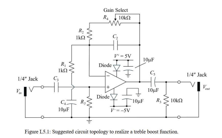
LTSpice Diagram
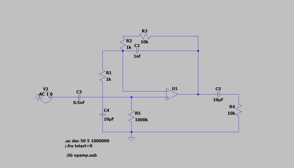
Following the suggest circuit, the values to be selected are C2, C3, and R5. In this case, I used C2=1nF, C3=0.5nF, R5=1MΩ.
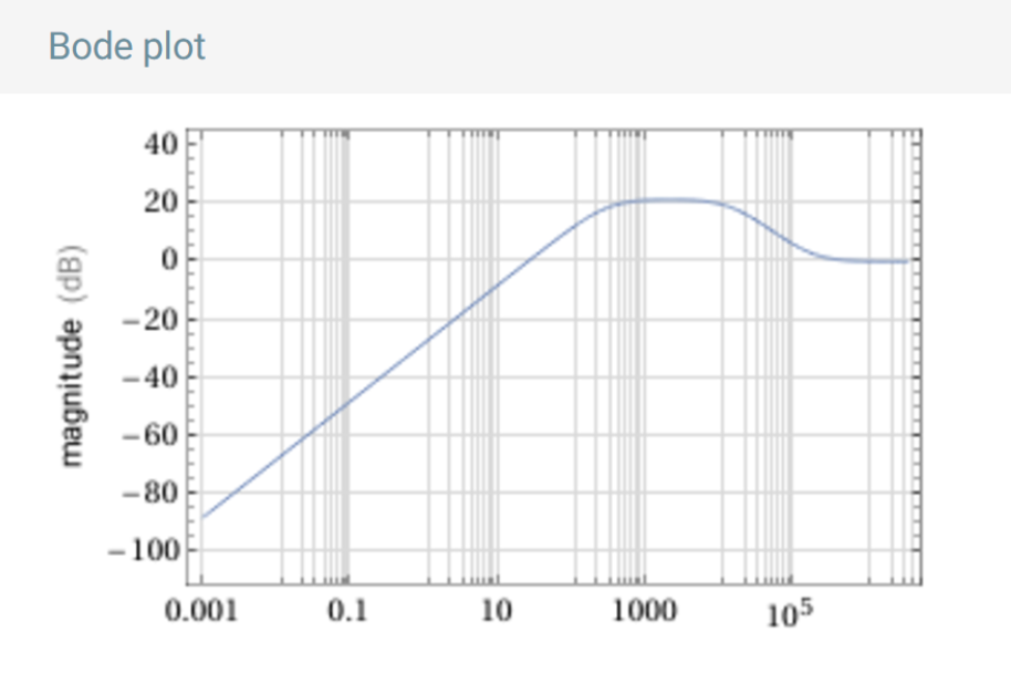
Transfer Function and Bode Plot
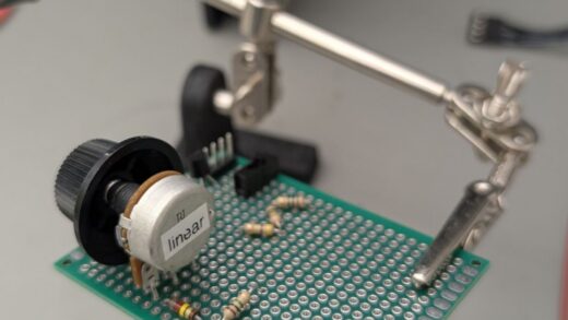
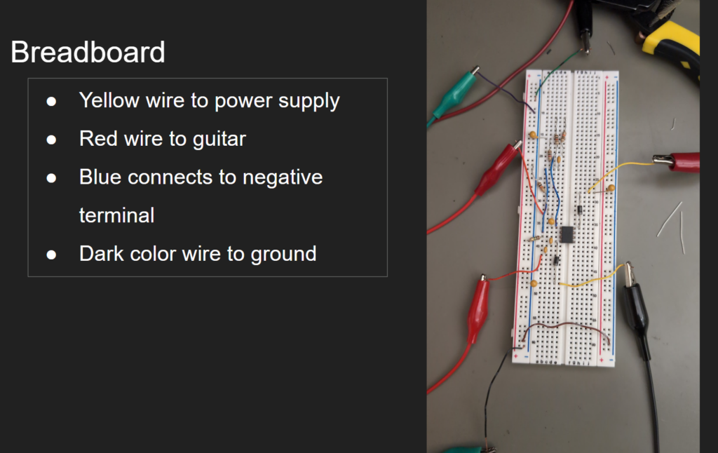
Breadboard
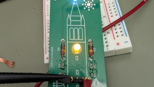
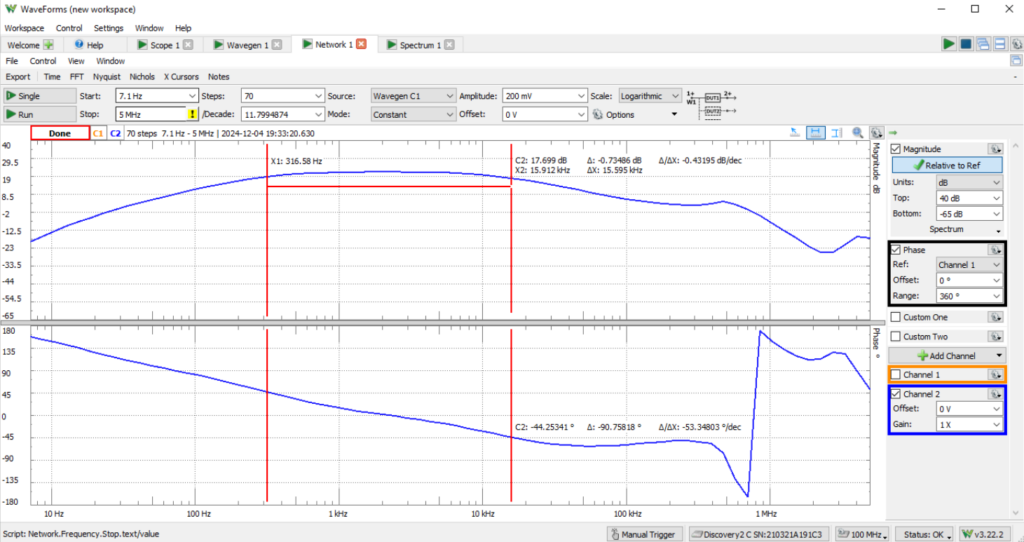
Test Result
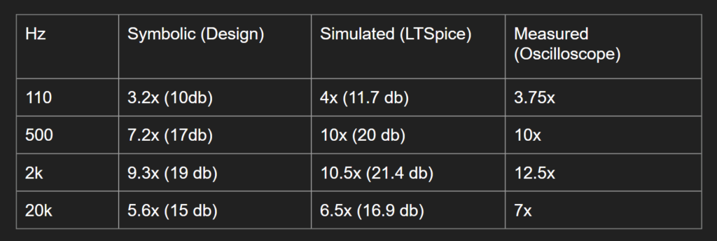
Reflection: In the design, we wanted to boost from 300hz to 15khz. In the lab, the high pass band actually starts from 318hz and ends at 14,468hz given our advertised values. Measured values are different because the components do not have the actual values.
Something that we discovered was that there was also a third frequency at 181khz that serves as a zero which keeps frequencies above 181khz at 0 db. No real function but interesting by-product.
When picking the capacitor C3 and R5, we also discovered that larger resistors and smaller capacitors perform better than larger capacitors with small resistors, allowing high frequencies to pass into the op-amp rather than shunting into ground, which a small resistor would do.