Midterm 1 Cheat sheet: front back
Work
Ohm’s Law
Power
Efficient Motor (80%)
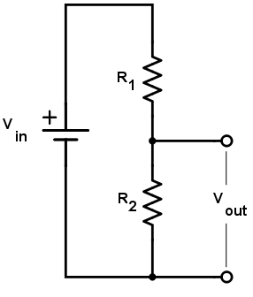
Voltage Divider
$$
\large
\boxed{V_{\text{out}} = V_{\text{in}}\frac{R_2}{R_1 + R_2}}
$$
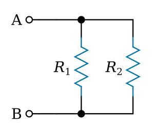
Parallel Resistance
$$
\large
\begin{aligned}
& R_{tot} = R_1 \parallel R_2 \\[15pt]
& \frac{1}{R_{tot}} = \frac{1}{R_1} + \frac{1}{R_2} \\[15pt]
& R_{tot} = \left( \frac{1}{R_1} + \frac{1}{R_2} \right)^{-1} \\[15pt]
& \boxed{ R_{tot} = \frac{R_1 R_2}{R_1 + R_2}}
\end{aligned}
$$
AC Power
1. AC power is half of DC power under the same peak voltage.
2. Instantaneous power pulsates at 2ω. But we care about average power.
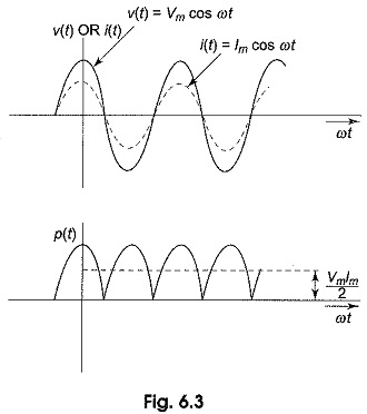
Top: voltage waveform
Bottom: AC Power waveform
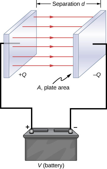
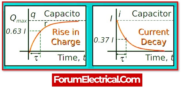
Capacitance details
Capacitor current derivation
First Differential Equations
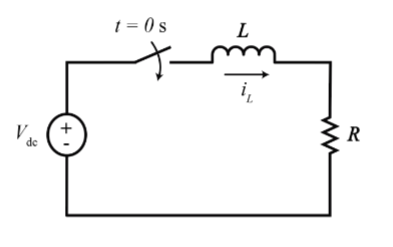
(1) Find \(I_L\) using KVL
$$ \begin{gathered} \begin{aligned} V_{dc} – V_L – V_R &= 0 \\[10pt] V_L = L \frac{di}{dt} \hspace{30pt} V_R &= I_L R \\[10pt] V_{dc} – L \frac{di}{dt} – I_L R &= 0 \\[10pt] L \frac{di}{dt} + I_L R &= V_{dc} \end{aligned} \\[15pt] \boxed{\text{(Standard form)} \hspace{15pt} \frac{di}{dt} + \frac{I_L R}{L} = \frac{V_{dc}}{L}} \end{gathered} $$(2) Homo./Natural Solution (remove \(V_{dc}\))
$$ \begin{gathered} \frac{di}{dt} + \frac{I_L R}{L} = 0 \\[15pt] I_L(t) = A e^{\frac{t}{L/R}} \end{gathered} $$(3) Particular/Steady Solution (remove \(\frac{di}{dt}\))
$$ \begin{gathered} \frac{I_L}{R} = \frac{V_{dc}}{R} \\[15pt] I_L = \frac{V_{dc}}{R} \longrightarrow \text{(B)} \end{gathered} $$(4) Initial Condition
$$ \begin{gathered} I_L(0) = A + B \\[10pt] 0 = A + B \\[10pt] -B = A \end{gathered} $$(5) Final Form (Natural + Steady state)
$$ \begin{gathered} I_L(t) = -\frac{V_{dc}}{R} e^{-\frac{t}{\tau}} + \frac{V_{dc}}{R} \\[15pt] \boxed{I_L(t) = \frac{V_{dc}}{R} \left(1 – e^{-\frac{t}{\tau}}\right)} \end{gathered} $$General Charging and Discharging
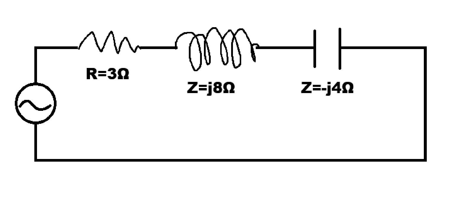
Impedance
\(I_C\) leads voltage by 90 degrees in time.
\(I_L\) lags voltage by 90 degrees in time.
Phasors
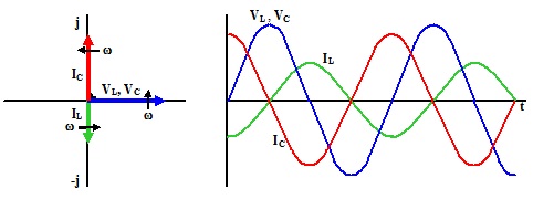
*Notice the zero crossings of the current vs the voltage to realize leading and lagging.
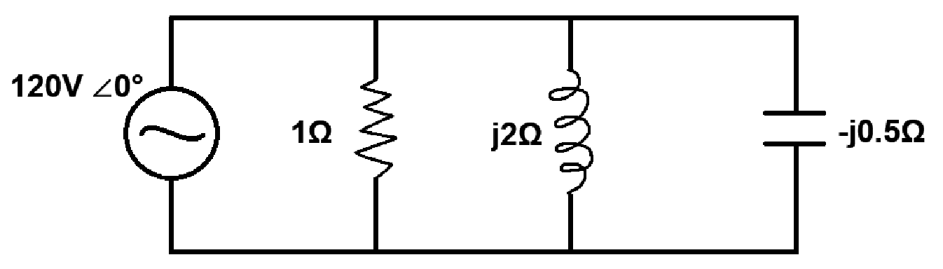
Complex Impedance

Complex Admittance
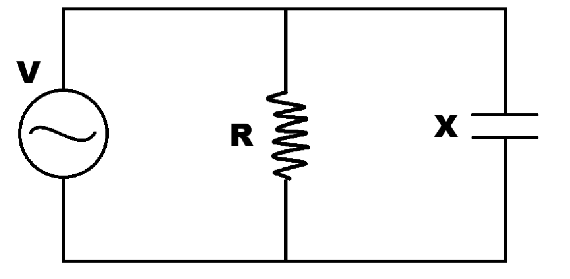
Parallel Case Using Admittance to Find Impedance
Series Circuit & Find admittance
*When trying to find reciprocal of complex Z or Y, much easier to do it in polar form with angles.
(Hard) Alternate method: Reciprocal Z or Y
Complex Power
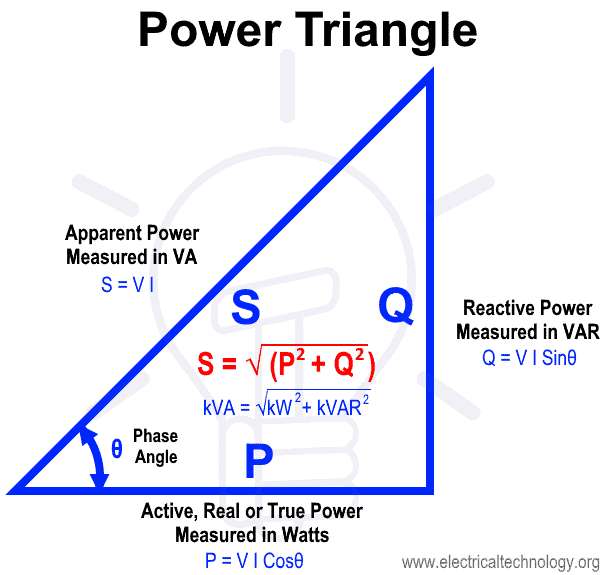
Apparent Power
$$ \begin{gathered} \boxed{\bar{S} = VI^* \quad \scriptsize{\text{[VA]}}} \\[10pt] \bar{S} = P + jQ \\[10pt] |\bar{S}| = \sqrt{P^2 + Q^2} \end{gathered} $$Power Factor
$$ \begin{gathered} \boxed{p.f = \cos(\theta)} \\[10pt] \boxed{p.f = \frac{P}{S}} \end{gathered} $$Reactive Power
$$ \begin{gathered} \begin{aligned} &\boxed{P = S \cdot \cos(\theta)} \\[10pt] &\boxed{Q = S \cdot \sin(\theta)} \\[10pt] &S = \frac{P}{\cos(\theta)}\\[10pt] &Q = P \cdot \tan(\theta) \end{aligned} \\[15pt] \end{gathered} $$Power \(\theta\)
$$ \begin{gathered} \theta = \cos^{-1}(\text{pf}) \\[10pt] \theta = \tan^{-1} \left(\frac{Q}{P} \right) \end{gathered} $$Power \(\theta\) Notes:
1. Positive power \(\theta\) = current lags voltage.
2. Negative power \(\theta\) = current leads voltage.
3. If Q or \(\theta\) is > 0, circuit is more inductive.
4. If Q or \(\theta\) is < 0, circuit is more capacitive.
5. If power \(|\theta|\) > 90°, load is a generator.
Complex Current
Finding Power in Parallel Circuit
Example: Reactive Power Compensation
Say our 3-phase complex power is \(S = 60.815\text{ kW} – j42.448\text{ kVAR}\), and we want to reduce our reactive power to zero. We need to provide more VAR. We need 3 equal capacitors and we want to find what size each are. There are two ways to do this.
First method: Find impedance (purely reactance) first using Ohm’s law \(X_C = \frac{V}{I}\). Phase current and voltage are used because we want to find the impedance of one capacitor on one of the loads on the delta configuration.
Second method: Find impedance (purely reactance) using the power law \(Q_C = \frac{V_\phi^2}{X_C}\), where \(Q\) is reactive power. This is similar to \(P = \frac{V^2}{R}\).
Total reactive power is divided by 3 simply because we have 3 loads in delta configuration, so each capacitor will provide 1/3 of the reactive power.